Soldering Iron
How to Solder: Through-Hole Soldering
Introduction
Soldering is one of the most fundamental skills needed to dabble in the world of electronics. The two go together like peas and carrots. And, although it is possible to learn about and build electronics without needing to pick up a soldering iron, you'll soon discover that a whole new world is opened with this one simple skill. We here at SparkFun believe that soldering should be a skill in everyone's arsenal. In a world of increasing technological surroundings, we believe it is important that people everywhere be able to not only understand the technologies they use everyday but also be able to build, alter, and fix them as well. Soldering is one of many skills that will empower you to do just that.

In this tutorial we will go over the basics of through-hole soldering
-- also known as plated through-hole soldering (PTH), discuss the tools
needed, go over techniques for proper soldering, and show you where you
can go from there. We will also discuss rework as it pertains to
through-hole soldering and give you some tips and tricks that will make
fixing any piece of electronics a breeze. This guide will be for
beginners and experts alike. Whether you've never touched an iron before
or are looking for a little refresher, this tutorial has a little
something for everyone.
What is Solder?
Before learning how to solder, it's always wise to learn a little bit about solder, its history, and the terminology that will be used while discussing it.
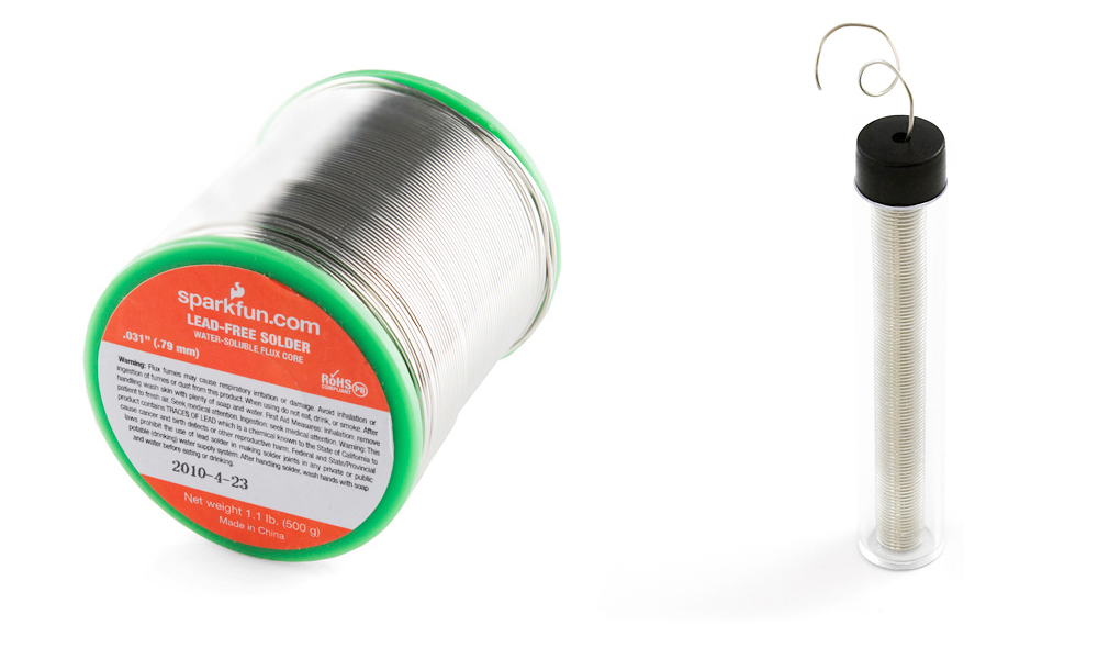
Solder, as a word, can be used in two different ways. Solder, the noun, refers to the alloy (a substance composed of two or more metals) that typically comes as a long, thin wire in spools or tubes. Solder, the verb, means to join together two pieces of metal in what is called a solder joint. So, we solder with solder!
Leaded vs. Lead-free Solder -- A Brief History
One of the most important things to be aware of when it comes to solder is that, traditionally, solder was composed of mostly lead (Pb), tin (Sn), and a few other trace metals. This solder is known as leaded solder. As it has come to be known, lead is harmful to humans and can lead to lead poisoning when exposed to large amounts. Unfortunately, lead is also a very useful metal, and it was chosen as the go-to metal for soldering because of its low melting point and ability to create great solder joints.
With the adverse effects of leaded soldering known, some key individuals and countries decided it was best to not use leaded solder anymore. In 2006, the European Union adopted the Restriction of Hazardous Substances Directive (RoHS). This directive, stated simply, restricts the use of leaded solder (amongst other materials) in electronics and electrical equipment. With that, the use of lead-free solder became the norm in electronics manufacturing.
Lead-free solder is very similar to its leaded counterpart, except, as the name states, it contains no lead. Instead it is made up of mostly tin and other trace metals, such as silver and copper. This solder is usually marked with the RoHS symbol to let potential buyers know it conforms to the standard.
Choosing the Right Solder for the Job
When it comes to manufacturing electronics, it's best to use lead-free solder to ensure the safety of your products. However, when it comes to you and your electronics, the choice of solder is yours to make. Many people still prefer the use of leaded solder on account of its superb ability to act as a joining agent. Still, others prefer safety over functionality and opt for the lead-free. SparkFun sells both varieties to allow individuals to make that choice for themselves.
Lead-free solder is not without its downfalls. As mentioned, lead was chosen because it performs the best in a situation such as soldering. When you take away the lead, you also take away some of the properties of solder that make it ideal for what it was intended -- joining two pieces of metal. One such property is the melting point. Tin has a higher melting point than lead resulting in more heat needed to achieve flow. And, although tin gets the job done, it sometimes needs a little help. Many lead-free solder variants have what's called a flux core. For now, just know that flux is a chemical agent that aids in the flowing of lead-free solder. While it is possible to use lead-free solder without flux, it makes it much easier to achieve the same effects as with leaded solder. Also, because of the added cost in making lead-free solder, it can sometimes be more expensive than leaded solder.
Aside from choosing leaded or lead-free solder, there are a number of other factors to consider when picking out solder. First, there are tons of other solder compositions out there aside from lead and tin. Check out the Wikipedia solder page for an extensive list of the different types. Second, solder comes in a variety of gauges, or widths. When working with small components, it's often better to use a very thin piece of solder -- the larger then number, the smaller the gauge. For large components, thicker wire is recommended. Last, solder comes in other forms besides wire. When getting into surface-mount soldering, you'll see that solder paste is the form of choice. However, since this is a through-hole soldering tutorial, solder paste will not be discussed in detail.
Purchasing Solder
SparkFun offers many sizes of spools of solder in both leaded and lead-free varieties. Whether you just need enough for one project or are stocking up for the coming winter, SparkFun has what you need. You can visit the Soldering category of the SparkFun catalog for more solder options as well.
Soldering Irons
There are many tools that aid in soldering, but none are more important than the soldering iron. If nothing else, you need at least an iron and some solder to accomplish the task at hand. Soldering irons come in a variety of from factors and range from simple to complex, but they all function roughly the same. Here, we'll discuss the parts of an iron and the different types of irons.
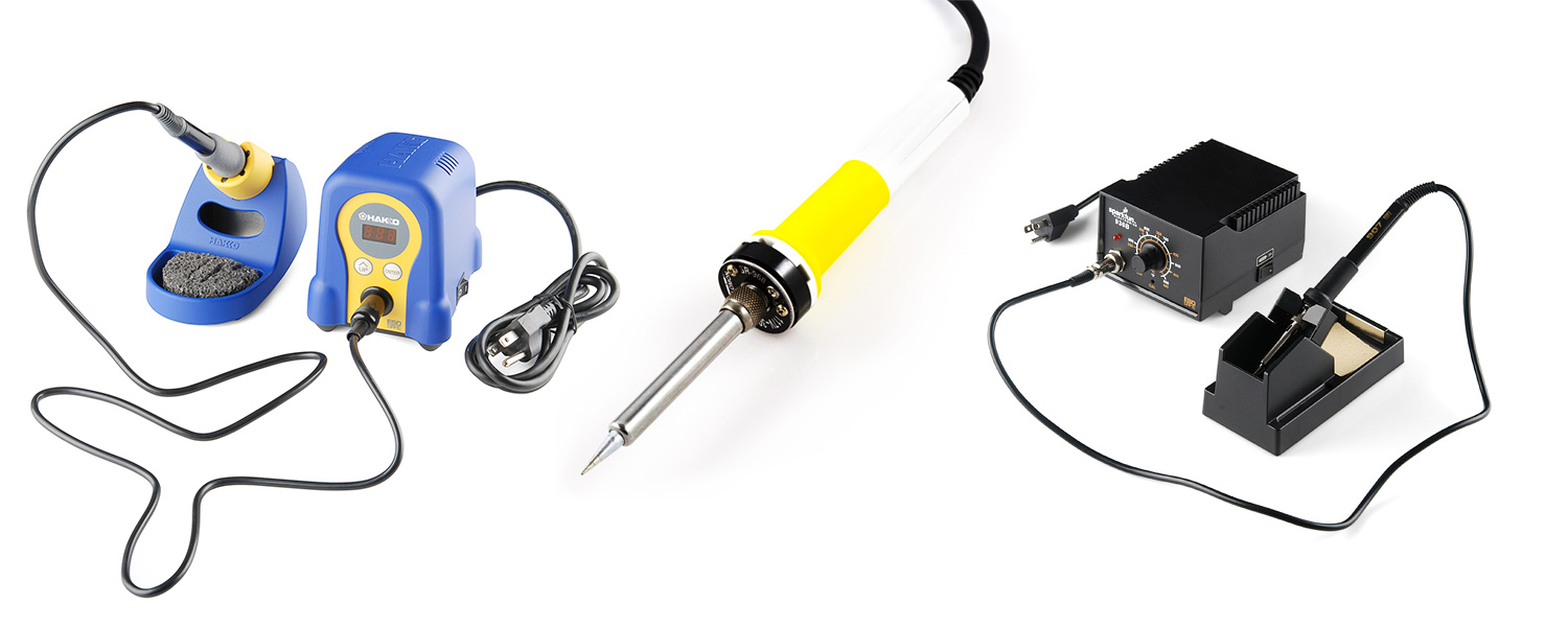
Soldering Iron Anatomy
Here are the basic parts that make up a soldering iron.
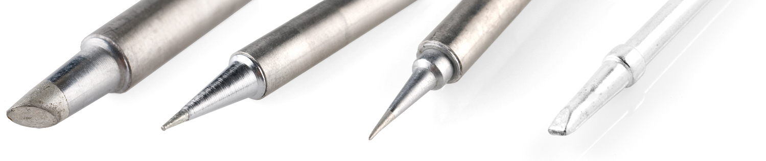
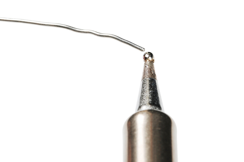
- Soldering Tips - No iron is complete without an iron tip. The tip is the part of the iron that heats up and allows solder to flow around the two components being joined. Although solder will stick to the tip when applied, a common misconception is that the tip transfers the solder. The tip actually transfers heat, raising the temperature of the metal components to the melting point of the solder, and the solder melts accordingly. Most irons give you the option to change your tip, should you need to replace an old tip or if you need to switch to a different style of tip. Tips come in a variety of sizes and shapes to accommodate any component.
Changing the tip is a simple process that consists of either unscrewing the wand or simply pushing in and pulling out the tip
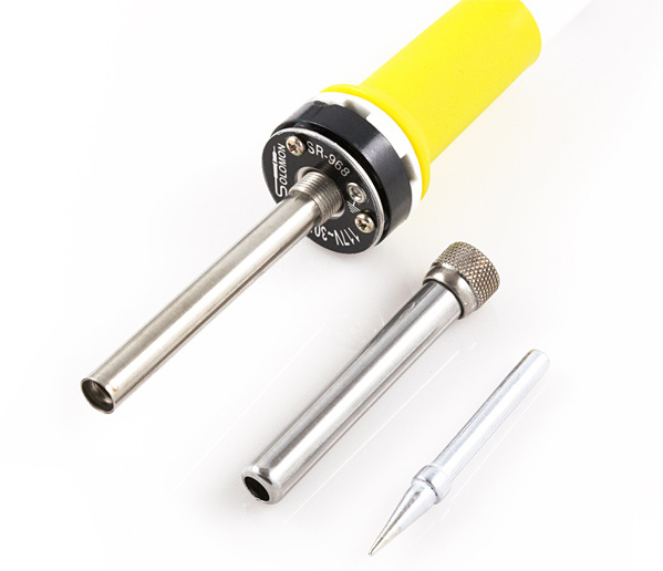
- Wand - The wand is the part of the iron that holds the tip. This is also the part that is handled by the user. Wands are usually made of a variety of insulating materials (such as rubber) to prevent the heat of the tip from transferring to the outside of the wand, but they also house wires and metal contacts that transfer heat from the base or outlet to the tip. This dual role of heating and preventing burns makes a high quality wand much appreciated.
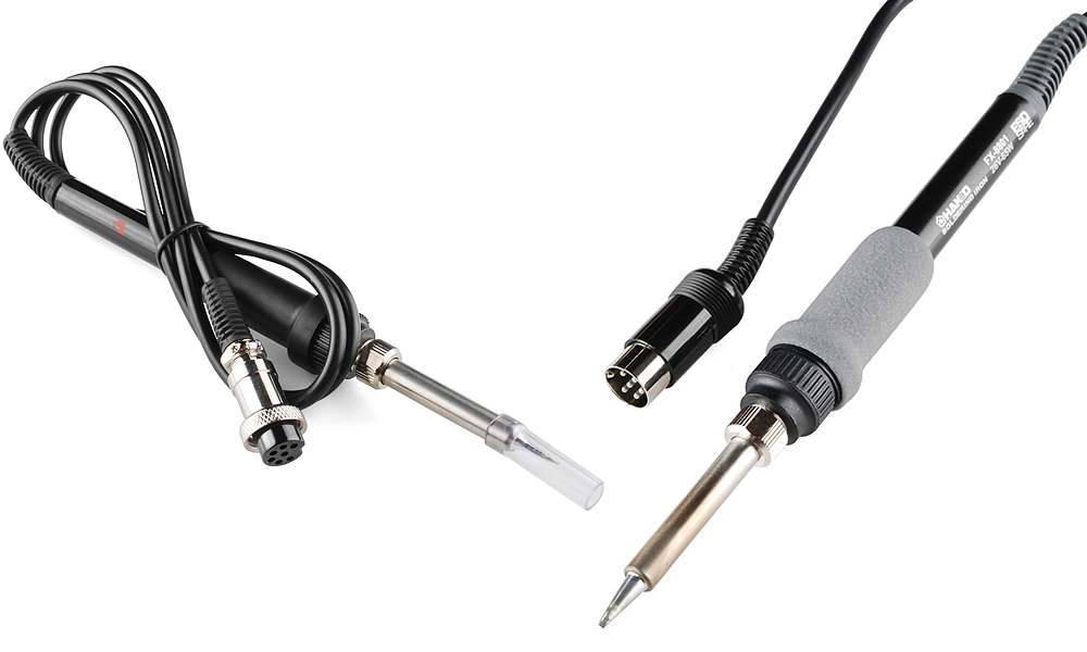
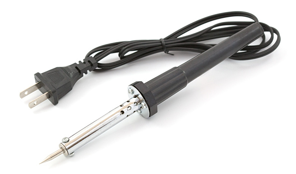
Some irons consist of just a wand that plugs into a wall outlet. These irons are as simple as they come, and they do not have any controls to vary the temperature. In these irons, the heating element is built directly into the wand.
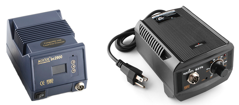
- Base - The base of the soldering iron is the control box that allows the adjusting of temperatures. The wand attaches to the base and receives its heat from the electronics inside. There are analog bases, which have a dial that controls the temperature, and there are digital bases, which have buttons to set the temperature and a display that tells you the current temperature. Some bases even have extra features such as heat profiles that allow you to quickly change the amount of heat provided to the tip for soldering a variety of components.
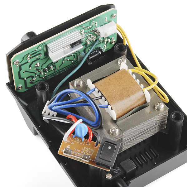
The base typically is comprised of a large transformer and several other control electronics that safely allow you to vary the heat of your tip.
- Stand (Cradle) - The iron stand (often referred to as a cradle) is what houses the iron when it is not in use. The stand may seem trivial, but leaving an unattended iron laying around on your desk or workbench is a potential hazard: it could burn you, or, worse, it could burn your desk and start a fire. Again, they can be as simple as a metal stand, or they can be complex, offering an auto-shutoff feature that reduces the temperature of the tip when the wand is placed in the cradle. This helps prevent the wearing of your tip over time.
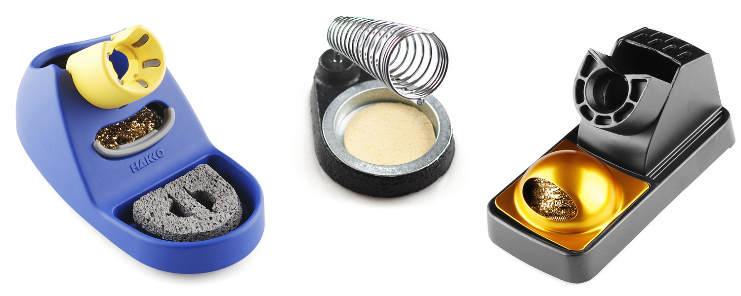
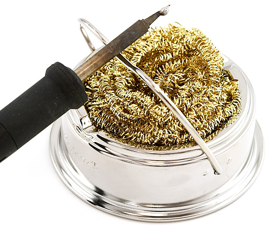
- Brass Sponge - As you solder, your tip will tend to oxidize, which means it will turn black and not want to accept solder. Especially with lead-free solder, there are impurities in the solder that tend to build up on the tip of your iron, which causes this oxidization. This is where the sponge comes in. Every so often you should give your tip a good cleaning by wiping off this build-up. Traditionally, an actual wet sponge was used to accomplish this. However, using a wet sponge can drastically reduce the lifespan of your tip. By wiping your tip on a cool, wet sponge, the tip tends to expand and contract from the change in temperature. This expansion and contraction will wear out your tip and can sometime cause a hole to develop in the side of the tip. Once a tip has a hole, it is no good for soldering. Thus, brass sponges have become the standard for tip cleaning. Brass sponges pull the excess solder from your tip while allowing the tip to maintain its current heat level. If you do not have a brass sponge, a regular sponge is better than nothing.
Tips and Tricks
Besides using a third arm, there are other methods of soldering components to boards. You will also run into issues that require different techniques to get the perfect solder joint. Check out some additional tips and tricks below!
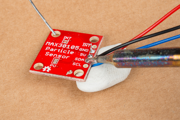
Tape or Sticky Tack to Hold Down Components
Got some tape or sticky tack? Try using it to hold down wires or headers against the board!
 |
|
| Sticky tack holding down wires for the MAX30105 particle sensor breakout board. |
Silicone or Pieces of Cardboard as Insulation
Need to hold down a component but it's getting too hot to hold down with your fingers against the board? You can always grab a piece of silicone or cut off a piece of cardboard to hold the component down for a few seconds. Below is an example of a resistor being held down on a shield with the help of piece of cardboard.
 |
Old Shields, Development Boards, and Breadboards as a Helping Hand
If you do not have a steady hand, you can use old shields and development boards to align headers before soldering. Here are two examples from the Arduino Shield tutorial when installing female stackable headers or male headers.
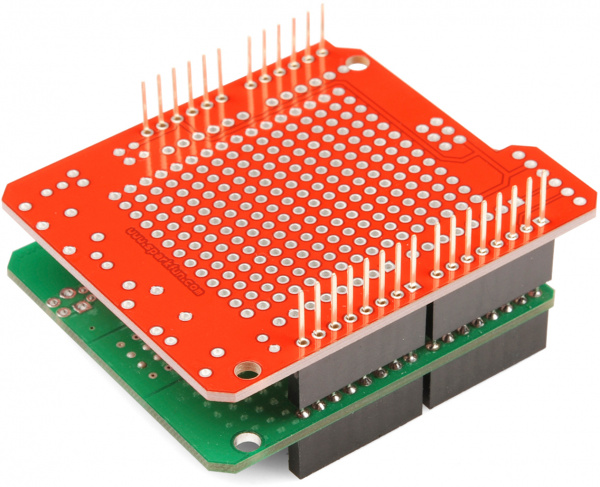 |
|
If you have a shield or breakout board can fit on a breadboard, you can use the breadboard to hold the pins as you solder as well. We recommend using this method with boards that have two rows of headers. You will want to avoid applying a lot of heat as this can melt the breadboard.
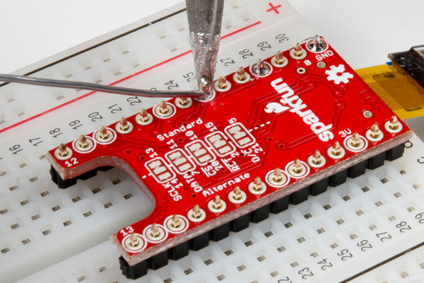 |
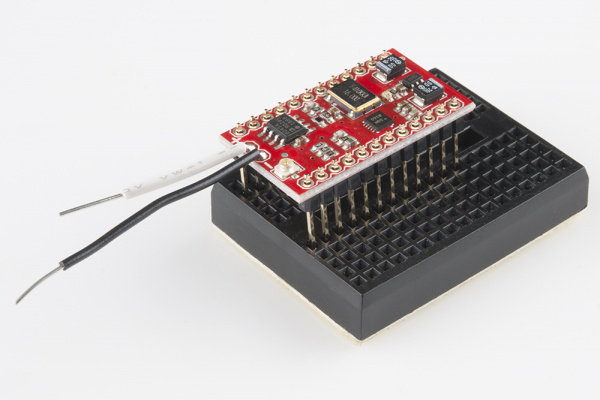 |
| Installing male headers on TeensyView shield for the Teensy with a breadboard. | Installing long male headers on the MiniGen shield for the Pro Mini with a mini-breadboard. |
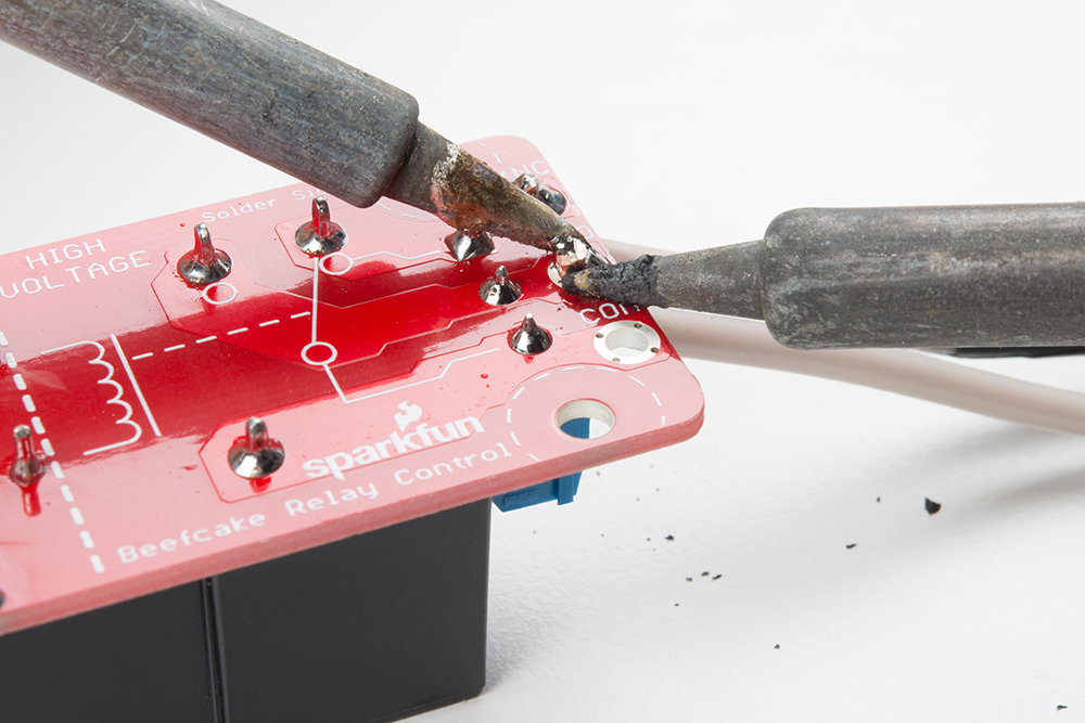
Ground Planes and Large Through Holes
Depending on the design, the plated through hole pad size may be connected to a ground plane or it's larger than usual. These require more heat. You may notice that the solder is kind of "sticking" but really, it's just blobbing up. You may need:
- larger soldering iron tip
- adjust the soldering station to a higher temperature (720 °F)
- add flux
- keep the soldering iron on the joint just a bit longer
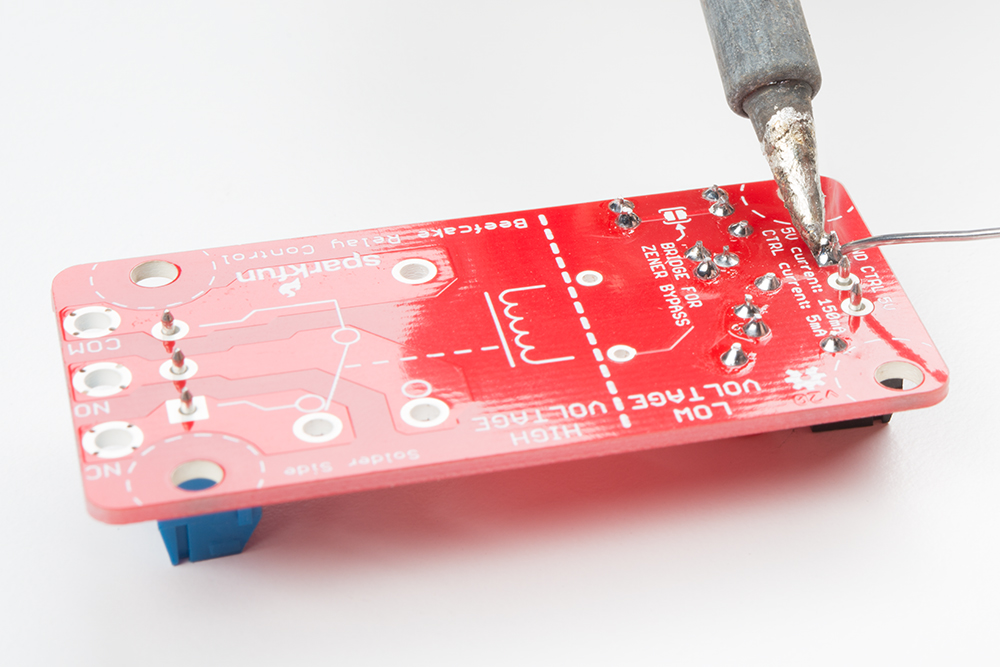 |
 |
| Soldering to a Ground Pin on the Beefcake Relay | Solder Blobbing Between Thick Wire and a Large Plated Through Hole on the Beefacke Relay |
Usually keeping adding some flux and keeping the soldering iron a little longer on the joint will help. Having a higher watt, adjustable soldering station usually helps with the tip recovering after it is in contact with something cold. If you have a friend or extra soldering iron around, you can also try to heat the joint with two soldering irons.
Advanced Techniques and Troubleshooting
Advanced PTH
Once you get the basics of creating good solder joints, it's time to learn some of the more advanced PTH techniques that you can utilize. This video goes over using flux, removing solder jumpers, desoldering components, along with some other tips and tricks.
Here are some other tips for PTH soldering:
Desoldering can often be the best way to learn how to solder. There are many reasons to desolder a part: repair, upgrade, salvage, etc. Many of the techniques used in the video aid in the desoldering process.
There is another method of removing solder from through-holes that we refer to as the slap method.
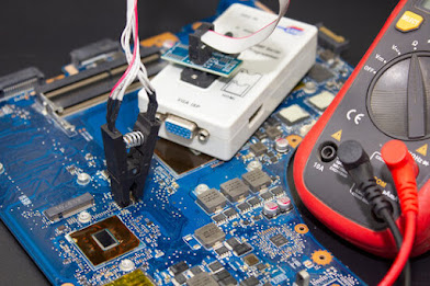
If you're ever unsure if the solder joint you created is making an electrical connection, you can use a multimeter to test for continuity.
Holding Headers Against a Board
For those that have the dexterity, you can install a row of headers by holding the pins against the board! You can try to use tape and sticky tack as mentioned earlier. Below is an example of installing female headers on the ProtoShield. However, you can follow along with male headers or use this technique to solder headers on any board.
Grab a female stackable header and slide it from the top side of a shield. With your soldering hand, pull the header with your index finger and thumb toward the edge of the board. Using your other hand, push against the header using your index finger and grip the board with your thumb. Hold the header down with your middle finger. Make sure to avoid touching any header pins where the soldering iron will touch.
 |
 |
Grab the soldering iron with your soldering hand and tack on one pin. Repeat for each header. After tacking one pin for each header, you will want to ensure that the pins are straight and perpendicular to your board. If they are not, you can try to reheat the header pin and adjust the header's alignment.
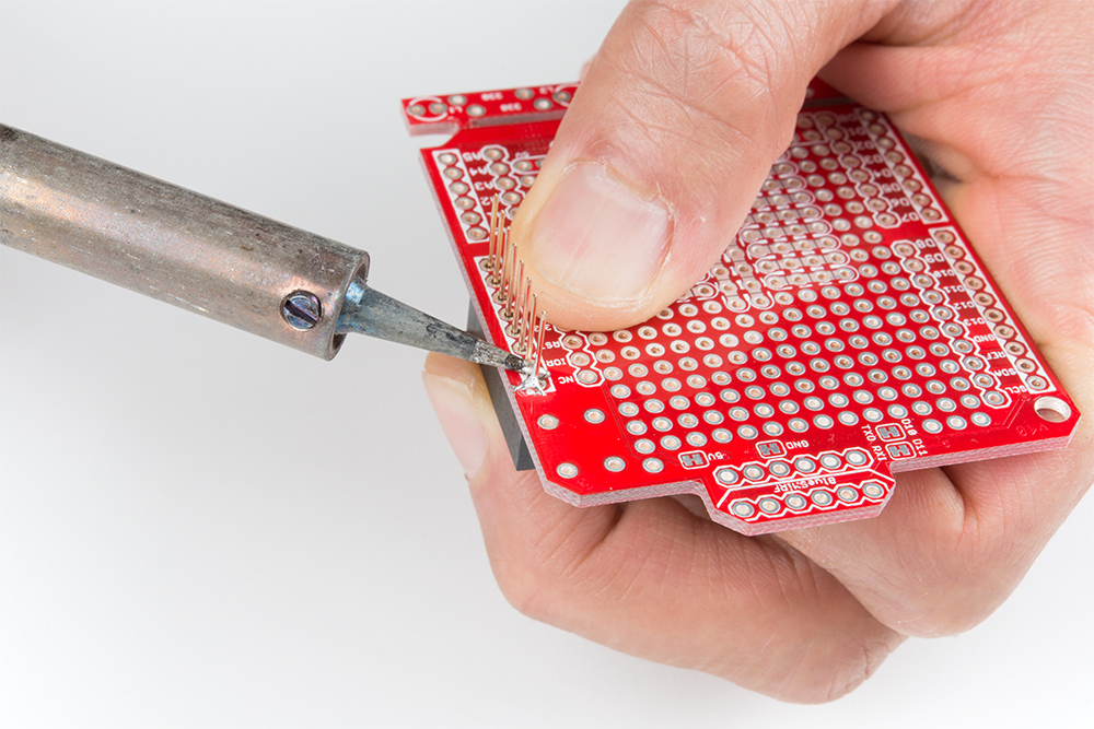
If the headers are aligned, you can solder the rest of the header pins on the board to finish installing the headers on the board!


Comments
Post a Comment